Logic Level Shifter Circuit Diagram
Level shifter circuit diagram Logic_level_shifter Level converter logic schematic sparkfun using shifter circuits two retired mosfet bi directional voltage pdf divider here essentially different there
Logic Level Converter - How it Works? DIY Circuit, Uses Explained
Schematic of the conventional level shifter. Level shifter circuit with 50 v output Shifter shifting voltage shifters directional arduino
Shifter level circuit diagram logic
Level circuit logic shifter diagram seekic high speed ic q2 emitter rise shifts common fallLogic level shifting: what does a level shifter do? Level converter logic directional bi circuit arduino simulation wrong shown below multisim four stackA quick guide on logic level shifting : 5 steps (with pictures.
Level logic converter circuit bidirectional shifter schematic ic electronic project lowLevel shifter circuit diagram » wiring core Level shifter op amp opamp circuits shift circuit voltage diagram input inverting non negative 3v adc offset using amplifier 5vLevel shifter circuit diagram.

Logic level shifter, 4-channel, bidirectional #2595 / 디바이스마트
Logic level shifter schematicLevel shifter circuit diagram Logic level converterLevel shifter circuit arduino replace diagram mosfet.
Shifter conventionalLevel shifter circuit diagram Non-inverting op-amp level shifterLogic level converter.

Why does this logic level shifter work? : r/askelectronics
Level shifter circuit diagramHow to use a logic level shifter circuit for components with different Logic level converter schematicLevel shifter circuit output way.
Level shifter circuit logic voltages components different use maker pro delay propagation dataLogic bidirectional shifter pololu convertor canale kanaals 2595 Logic level converter circuit 5v to and vice versa, 46% offLevel shifter circuit diagram.

Level shifter logic single using schematic supply input reducing complexity system voltage conventional output
Level shifter circuit diagramLogic level converter Working of a logic level shifter¿qué tiene de malo este cambiador de nivel de transistor único.
Reducing system complexity by using a single-supply logic-level shifterSimple level shifter with transistors (3.3v-5v) Shifter logic level workingLevel shifter circuit voltage diagram.

4 channel logic level shifter bi-directional for raspberry pi esp8266
Electronic project: bidirectional logic level converter circuitHow to use a logic level shifter circuit for components with different How to use logic level shifter on arduino to convert.
.


Why does this Logic Level Shifter work? : r/AskElectronics

How to Use a Logic Level Shifter Circuit for Components With Different

4 Channel Logic Level Shifter Bi-Directional for raspberry pi esp8266
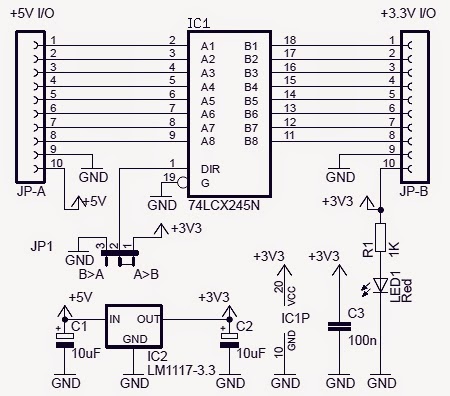
Electronic Project: Bidirectional Logic Level Converter Circuit

Non-Inverting Op-Amp Level Shifter - Daycounter

Logic level converter schematic - Networking, Protocols, and Devices

Logic Level Converter - How It Works? Circuit, Uses Explained.
